- Laminated Busbar
- Film Capacitor
- Film Capacitor for HEV / EV Motor Control Unit
- DC-Link Capacitor ( Dry-Type, Plastic Case, Maximum Temperature 85℃)
- DC-Link Capacitor ( Dry-Type, Plastic Case, Maximum Temperature 105℃)
- MKP DC-Link Film Capacitor
- Water Cooled Heat Sink
- Flat Heat Pipe
- Reactor
- Water Cooling Reactor
- Input AC Reactor
- Output AC Reactor
- DC Reactor
- Reactor for Explosion-Proof Inverter
- Sine Wave Filter
- Detuned Reactor
- DV/DT Filters
- Three-Phase Input Filter
- Resistor
- Wirewound Resistor
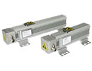
- Aluminum Enclosure Resistor
- Aluminum Housed Resistor
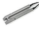
- Die-Casting Aluminum Resistor
- Aluminium Resistor (Multiple Unit)
- Thick Film Resistor
- Braking Resistor Box
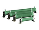
- Wirewound Tubular Fixed Resistor
- Power Resistor Unit
- Crowbar Resistor
- Braking Unit
Crowbar Resistor
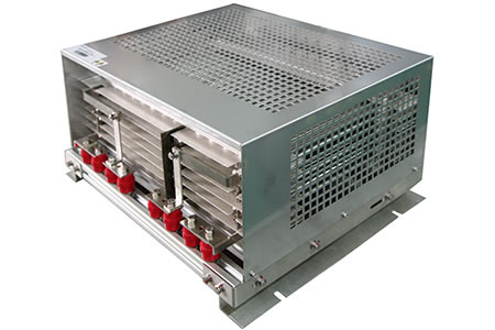

Product Profile
This crowbar resistor is mainly applied in the technology of low voltage ride through in the wind power generation inverter. Installed at the side of the wind power generator rotor, it works as a current transformer at the bypass rotor side. While low-voltage disturbance occurs in the power grid, it can prevent the over-high voltage of the DC bus and the ultra strong rotor current. It is mainly used for the fault state and damped stator flux linkage. The crowbar resistor can dissipate huge amount of energy instantaneously.
Evaluation of the Service Life of the Crowbar Resistor
(The form takes 1.5WM windmill generator as an example and the environmental temperature is below60℃)
| 200J | 1 time/second | |
| 220KJ | 1time/30minutes | 350,000 times (a service life of 20 years) |
| 640KJ | 1time/week | 1,000 times (a service life of 20 years) |
| 1360KJ | 1time/month | 250 times (a service life of 20 years) |
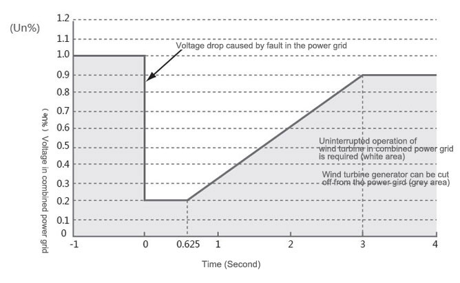
Requirements for the low voltage ride through of wind turbine generator
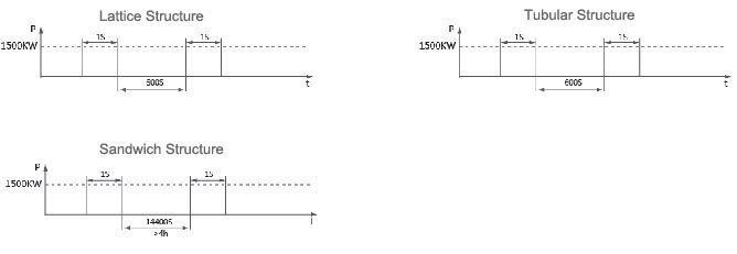
Crowbar Electrical Resistor Classification
Lattice Structure: Natural Air Cooling
M: Quality of Resistance Material. Unit: Kg
Q: Energy Absorbed by Resistance Material. Unit KJ
C: Specific Heat Capacity of Resistance Material. Unit: KJ/Kg K
Δt: Temperature Rise of the Resistance Material. Unit: K
Take 1.5 MW Wind Driven Generator as Example:
Resistance Material: SUS304
Qmax =1360KJ C=0.5kJ/kg•K Δt =400K
M=1360/ (0.5×400) =6.8Kg
Weight of Resistance Material: About 6.8Kg
Weight of Auxiliary Material: About 20Kg
Sandwich Structure: Natural Air Cooling
M: Quality of Resistance Material. Unit: Kg
Q: Energy Absorbed by Resistance Material. Unit: KJ
C: Specific heat capacity of Resistance Material. Unit: KJ/Kg
ΔT: Temperature Rise of the Resistance Material. Unit: K
Take 1.5 MW Wind Driven Generator as Example:
Resistance Material: SUS304
Qmax=1360KJ C=0.5kJ/kg•K Δt=400K
M=1360/ (0.5×400) =6.8Kg
Weight of Resistance Material: About 6.8 Kg
Weight of Auxiliary Materials: About 20Kg
Volume: 500×450×150 (mm)
Tubular Structure: Natural Air Cooling
M: Quality of Resistance Material. Unit: Kg
Q: Energy Absorbed by Resistance Material. Unit: KJ
C: Specific Heat Capacity of Resistance Material. Unit: KJ
Δt: Temperature Rise of Resistance Material. Unit: K
Take 1.5 MW Wind Driven Generator as Example
Resistance Material: SUS304
Qmax=1360KJ C=0.5KJ/Kg•K Δt =400K
M=1360/ (0.5×400) =6.8Kg
Weight of Resistance Material: About 6.8 Kg
Weight of Auxiliary Material: About 12 Kg
A Comparison of Working Condition
 Structural Comparison
| Weight (Kg) | Volume Size (mm) | Real Temperature Rise (℃) | Price | |
| Lattice Structure | 26 | 500×450×150 | 450 | Medium |
| Sandwich Structure | 28 | 491×320×200 | 200 | Low |
| Tube-type Structure | 18 | 600×350×400 | 400 | Medium to low |
| Type | Density(g/mm) | Resistivity (Ω·mm /m) | Heat capacity(J/g·K) | Thermal conductivity(w/m · ° C ) | Temperature coefficient (ppm/ ° C ) |
| SUS304 | 0.008 | 0.68 | 0.5 | 13.2 | < 1400 |
| SUS316 | 0.008 | 0.73 | 0.45 | 13.23 | < 900 |
| SUS310 | 0.008 | 0.71 | 0.46 | 13.2 | < 600 |
| Cr20Ni80 | 0.0084 | 1.09 | 0.441 | 16.0 | < 100 |
The Resistance Value of the Braking Resistor: R
The Resistance Value of the Braking Resistor: 
The chopper wave voltage value of the braking circuit of the selected transducer
K: the required multiple of the braking torque: 12-2.0K
P: the power of the selected transducer
The power of the braking resistor: Pr= 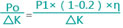
Po: the power of electric motor
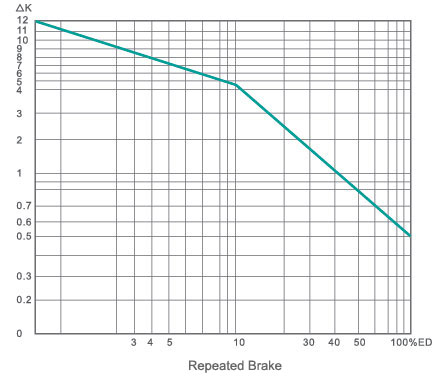
Δ K: The allowed multiple of overload of the braking resistor in short working time. The specific data should be based on the actual working condition.
P1: The average power required by the system
h: Transminssion efficiency. The mechanical system of transmission provides a braking damp of 0.2 which corresponds to the efficiency and the internal resistance of the electro motor consumes 20% of the braking energy
ED brake ratio is the percentage of braking time based on a 100-second operating cycle. The selection of brake unit shall be carried out in accordance with brake current Udc/R and brake ratio ED
The overload of the reactor is allowed to exceed the following multiples.
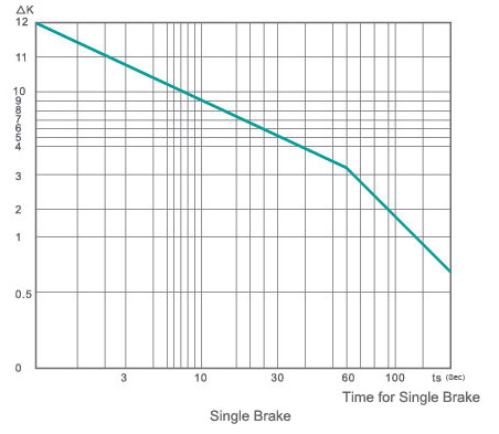
The number of folds that reactor's overload is allowed to exceed